Weld Lines, Knit Lines and Meld Lines
A weld line (weld point,
flow line or a knit line) forms when separate melt fronts travelling
in opposite directions meet. A meld line occurs when two moving
melt fronts converge and flow parallel to each other. Weld and
meld lines are generally caused by holes or inserts in the part,
multiple gates, variable wall thickness or hesitation and race
track effects.

| 1.
The Initial Weld Point |
|
2.
Section through Weld Point |
 |
|
 |
The
wall thickness of this example is un-even, causing the
weld point to form offset from the centre of the rectangular
hole.
|
|
A
section through the weld point shows the melt fronts meeting
at the centre point of the flow channel where the material
is hottest.
|
| 3.
Temperature Profile Section |
|
4.
Flow Front Temperature |
 |
|
 |
Typical
fountain flow results in a hot core of polymer flowing
through the centre to the flow front and a frozen layer
at the mould wall. Incomplete joining of the frozen layer
influences weld line visibility. |
|
Un-even
wall thickness causes the flow front temperature to reduce
on the left side of the aperture.
A variation in temperature usually increases the visibility
of the weld line. |
| 5.
Flow Direction @ Weld Point |
|
6.
Flow front angle @ 135º |
 |
|
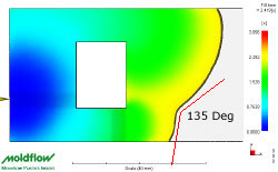 |
The
flow direction plot above, shows the change in direction
of the melt fronts as the weld point forms. The weld point
turns into a "meld" as the flow fronts converge
and flow together. |
|
At
the initial point of contact the weld is almost always
visible. Once the angle of the merging flow fronts passes
135º, the weld changes to a "meld" where the
flow fronts move in parallel. see below: |
The Flow Front Meeting Angle
Traditionally,
a "meeting angle" of 135º is used to differentiate between
weld lines and meld lines, as illustrated in Figure 6.
For most polymers the weld line surface mark tends to
reduce once the meeting angle passes through 120º to 150º.
However, there is always an exception to the rule and
some materials by nature tend to exhibit more visible
weld lines irrespective of the angle. In addition many
fillers and additives also highlight weld & meld lines.
Glass fibres and metallic pigments are good examples. Typical
fountain flow results in a hot core of polymer flowing
through the centre to the flow front and a frozen layer
at the mould wall. Incomplete joining of the frozen layer
influences weld line visibility, therefore mould temperature
and melt temperature are key factors influencing weld
line visual quality and strength.
The exact strength of the weld line depends on the ability
of the flow fronts to weld (or knit) to each other. The
strength of the weld-line area can range from 10 to 90
percent as strong as the pure material. Weld lines are
generally considered to be of lower quality than meld
lines, since less molecular diffusion occurs across a
weld line after it is formed.
Conditions
that are favorable for better weld-line strength include:
High injection pressure and speed; High melt and mold-wall
temperature; Formation of the weld lines closer to the
gate; A temperature difference of less that 10ºC between
the two emerging melt fronts.
If
a weld line forms before the filling phase is complete
and is immediately subject to additional packing pressure,
the weld line will typically be less visible and stronger. The most effective
way to improve the strength of weld and meld lines is
by increasing the local temperature and pressure.
For more information or a quotation please see our contact and RFQ pages.
|